
Page 322 - Engineering Digital Design
P. 322
PROBLEMS 293
(c) Implement the results of part (b) by making use of Eq. (6.22). Is an eq input
necessary?
6.29 Given the block symbol for a 4-bit cascadable comparator in Fig. 6.30 and with the
appropriate gate-minimum NAND/EQV/INV external logic, design a 5-bit cascadable
comparator. (Hint: Use the 1-bit comparator as the output (MSB) stage.)
6.30 Design a 4-bit even-parity detector with respect to logic 1 by using only XOR gates
(nothing else). Show how this result can be used to produce a 4-bit odd-parity detector
without adding additional hardware.
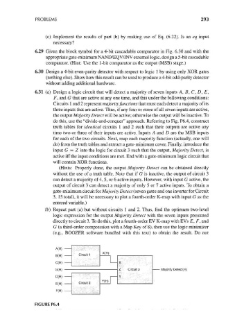
6.31 (a) Design a logic circuit that will detect a majority of seven inputs A, B, C, D, E,
F, and G that are active at any one time, and this under the following conditions:
Circuits 1 and 2 represent majority functions that must each detect a majority of its
three inputs that are active. Thus, if any four or more of all seven inputs are active,
the output Majority Detect will be active; otherwise the output will be inactive. To
do this, use the "divide-and-conquer" approach. Referring to Fig. P6.4, construct
truth tables for identical circuits 1 and 2 such that their outputs are active any
time two or three of their inputs are active. Inputs A and D are the MSB inputs
for each of the two circuits. Next, map each majority function (actually, one will
do) from the truth tables and extract a gate-minimum cover. Finally, introduce the
input G = Z into the logic for circuit 3 such that the output, Majority Detect, is
active iff the input conditions are met. End with a gate-minimum logic circuit that
will contain XOR functions.
(Hints: Properly done, the output Majority Detect can be obtained directly
without the use of a truth table. Note that if G is inactive, the output of circuit 3
can detect a majority of 4, 5, or 6 active inputs. However, with input G active, the
output of circuit 3 can detect a majority of only 5 or 7 active inputs. To obtain a
gate-minimum circuit for Majority Detect (seven gates and one inverter for Circuit
3, 15 total), it will be necessary to plot a fourth-order K-map with input G as the
entered variable.)
(b) Repeat part (a) but without circuits 1 and 2. Thus, find the optimum two-level
logic expression for the output Majority Detect with the seven inputs presented
directly to circuit 3. To do this, plot a fourth-order EV K-map with EVs £, F, and
G (a third-order compression with a Map Key of 8), then use the logic minimizer
(e.g., BOOZER software bundled with this text) to obtain the result. Do not
A(H)
X(H)
B(H) Circuit 1
C(H) X
G(H) Z Circuit 3 Majority Detect(H)
D(H) Y
Y(H)
E(H) Circuit 2
F(H)
FIGURE P6.4