
Page 325 - Engineering Digital Design
P. 325
296 CHAPTER 7 / PROGRAMMABLE LOGIC DEVICES
> r
— » !
'o ^ n-to-2n ^ l ~* °o
n-to-2n
— + Address — * OR Memory
n Address Decoder Array . > m Outputs
Inputs (non- (programmable)
nrnnrammahlfi^
—> - O m -i/
n
2 x m ROM
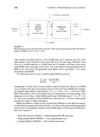
FIGURE 7.1
Block diagram showing the fixed address decoder (AND) stage and the programmable OR memory
stage for a ROM of size 2" words x m bits.
input variables are called addresses, and in ROMs there are 2" minterm code lines, each
representing a coded minterm on the output side of the decoder stage. Therefore, since
there are n possible addresses to a ROM, there are 2" possible words that can be stored
in the ROM, each word being m bits in size. Any m-bit output word programmed into the
ROM can be selected by the appropriate input address and is nonvolatile — it is stored
permanently in the ROM.
The dimensions and size of an n-input/m-ouptut ROM are given by
n
2" xm = (2 )(m)bits
Dimensions §j ze
meaning that 2" words, each of m bits, produce a total of (2")(m) bits. The size of a ROM
3
may be rounded off to the nearest integer power of 2 in K (10 ) bits of ROM. For example,
8
an 8-input/4-output ROM is represented as a 2 x 4 = 256 x 4 bit = 1,024 bit or IKbit
ROM. The problem with the bit-roundoff form of representation is that knowledge of the
6
7
dimensions is lost. Thus, a IKbit ROM could be any of the following: 2 x 8 = 2 x 16,
etc. This can be avoided by giving the ROM size in dimension (2" x m) form, which clearly
specifies the number of inputs and outputs.
ROMs may differ in a variety of ways, but the main differences center about the manner
in which they are programmed, and on whether or not they can be erased and reprogrammed
and how this is accomplished. Members of the ROM family of PLDs may be divided into
three main categories:
• Read-only memories (ROMs) — Mask programmable OR stage only
• Programmable ROMs (PROMs) — User programmable once
• Erasable PROMs (EPROMs) — User erasable many times