
Page 329 - Engineering Digital Design
P. 329
300 CHAPTER 7 / PROGRAMMABLE LOGIC DEVICES
Symbolic
OR Matrix
AB A 1 A 0 B, B 0 A>B A=B A<B
00 0 0 0 0 0 1 0
01 0 0 0 1 0 0 1
02 0 0 1 0 0 0 1
03 0 0 1 1 0 0 1
10 0 1 0 0 1 0 0
11 0 1 0 1 0 1 0
Stores a
12 0 1 1 0 0 0 1 0(L)
13 0 1 1 1 0 0 1
20 1 0 0 0 1 0 0
21 1 0 0 1 1 0 0
22 1 0 1 0 0 1 0 Stores a
23 1 0 1 1 0 0 1
30 1 1 0 0 1 0 0
31 1 1 0 1 1 0 0
32 1 1 1 0 1 0 0
33 1 1 1 1 0 1 0
(a) EN(L)
A>B A=B A<B
(H) (H) (H)
(b)
FIGURE 7.4
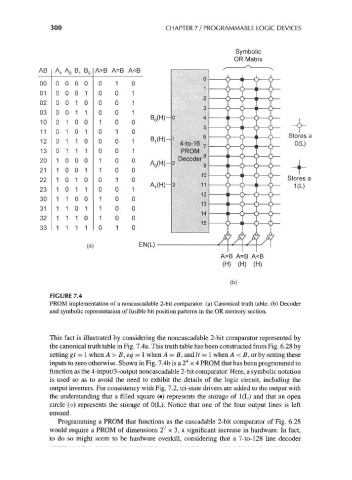
PROM implementation of a noncascadable 2-bit comparator, (a) Canonical truth table, (b) Decoder
and symbolic representation of fusible bit position patterns in the OR memory section.
This fact is illustrated by considering the noncascadable 2-bit comparator represented by
the canonical truth table in Fig. 7.4a. This truth table has been constructed from Fig. 6.28 by
setting gt = 1 when A > B, eq = 1 when A = B, and It = 1 when A < B, or by setting these
4
inputs to zero otherwise. Shown in Fig. 7.4b is a 2 x 4 PROM that has been programmed to
function as the 4-input/3-output noncascadable 2-bit comparator. Here, a symbolic notation
is used so as to avoid the need to exhibit the details of the logic circuit, including the
output inverters. For consistency with Fig. 7.2, tri-state drivers are added to the output with
the understanding that a filled square (•) represents the storage of 1(L) and that an open
circle (o) represents the storage of 0(L). Notice that one of the four output lines is left
unused.
Programming a PROM that functions as the cascadable 2-bit comparator of Fig. 6.28
7
would require a PROM of dimensions 2 x 3, a significant increase in hardware. In fact,
to do so might seem to be hardware overkill, considering that a 7-to-128 line decoder