
Page 148 - Industrial Process Plant Construction Estimating and Man Hour Analysis
P. 148
Diesel power plant Chapter 7 123
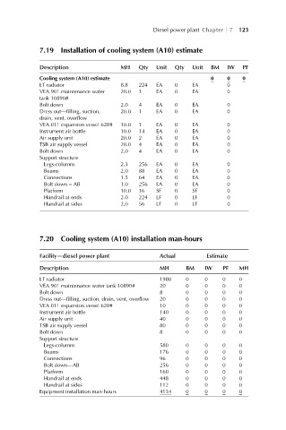
7.19 Installation of cooling system (A10) estimate
Description MH Qty Unit Qty Unit BM IW PF
Cooling system (A10) estimate 0 0 0
LT radiator 8.8 224 EA 0 EA 0
VEA 901 maintenance water 20.0 1 EA 0 EA 0
tank 10890#
Bolt down 2.0 4 EA 0 EA 0
Dress out—filling, suction, 20.0 1 EA 0 EA 0
drain, vent, overflow
VEA 011 expansion vessel 628# 10.0 1 EA 0 EA 0
Instrument air bottle 10.0 14 EA 0 EA 0
Air supply unit 20.0 2 EA 0 EA 0
TSB air supply vessel 20.0 4 EA 0 EA 0
Bolt down 2.0 4 EA 0 EA 0
Support structure
Legs-columns 2.3 256 EA 0 EA 0
Beams 2.0 88 EA 0 EA 0
Connections 1.5 64 EA 0 EA 0
Bolt down – AB 1.0 256 EA 0 EA 0
Platform 10.0 16 SF 0 SF 0
Handrail at ends 2.0 224 LF 0 LF 0
Handrail at sides 2.0 56 LF 0 LF 0
7.20 Cooling system (A10) installation man-hours
Facility—diesel power plant Actual Estimate
Description MH BM IW PF MH
LT radiator 1980 0 0 0 0
VEA 901 maintenance water tank 10890# 20 0 0 0 0
Bolt down 8 0 0 0 0
Dress out—filling, suction, drain, vent, overflow 20 0 0 0 0
VEA 011 expansion vessel 628# 10 0 0 0 0
Instrument air bottle 140 0 0 0 0
Air supply unit 40 0 0 0 0
TSB air supply vessel 80 0 0 0 0
Bolt down 8 0 0 0 0
Support structure
Legs-columns 580 0 0 0 0
Beams 176 0 0 0 0
Connections 96 0 0 0 0
Bolt down—AB 256 0 0 0 0
Platform 160 0 0 0 0
Handrail at ends 448 0 0 0 0
Handrail at sides 112 0 0 0 0
Equipment installation man-hours 4134 0 0 0 0