
Page 272 - Introduction to Computational Fluid Dynamics
P. 272
P1: KsF/ICD
0 521 85326 5
CB908/Date
0521853265c08
8.5 UNSTRUCTURED MESH GENERATION
I = IN = 9 May 10, 2005 16:28 251
J = JN = 5 EAST
36 27 18 9
45
64 48 32
16
63 47
44 35 31
26 17
62 15
43
42 61 46 8
30 14
NORTH 41 59
34 45
58 60
40
38 39 44 16 13
37 57 33 29
54 55 25 7
50 51 43 28 12
49 56 32
28 52 53 27
29 30 31 41 42 24
33 40 11
WEST 36 26 15
19 34 37
35 38 39 23 10 6
20 21 25
22
17 18 14
10 24 9
19 22 23
11 8 SOUTH
1 20 12 21 13
I = 1 5
2 4 5 6 7
3
J = 1
2
4
3
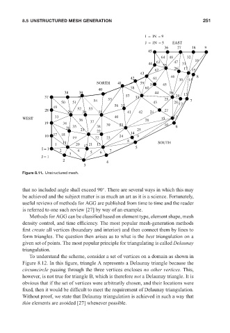
Figure 8.11. Unstructured mesh.
◦
that no included angle shall exceed 90 . There are several ways in which this may
be achieved and the subject matter is as much an art as it is a science. Fortunately,
useful reviews of methods for AGG are published from time to time and the reader
is referred to one such review [27] by way of an example.
Methods for AGG can be classified based on element type, element shape, mesh
density control, and time efficiency. The most popular mesh-generation methods
first create all vertices (boundary and interior) and then connect them by lines to
form triangles. The question then arises as to what is the best triangulation on a
given set of points. The most popular principle for triangulating is called Delaunay
triangulation.
To understand the scheme, consider a set of vertices on a domain as shown in
Figure 8.12. In this figure, triangle A represents a Delaunay triangle because the
circumcircle passing through the three vertices encloses no other vertices. This,
however, is not true for triangle B, which is therefore not a Delaunay triangle. It is
obvious that if the set of vertices were arbitrarily chosen, and their locations were
fixed, then it would be difficult to meet the requirement of Delaunay triangulation.
Without proof, we state that Delaunay triangulation is achieved in such a way that
thin elements are avoided [27] whenever possible.