
Page 197 - Sami Franssila Introduction to Microfabrication
P. 197
176 Introduction to Microfabrication
O O O O O
O O O O O O O O
Si Si Si Si Si
3.18 Å
O
O
O
O
O
Si O O Si O O Si O Si O Si O
O
O
O
O
O
◦
◦
Figure 17.5 Viscous flow of oxide (800 C for native oxide, 1000 C for grown oxides). Source: Tong, Q.Y. & U.
G¨ osele, Semiconductor Bonding, Wiley, 1999. This material is used by permission of John Wiley & Sons, Inc
3000 Surface preparation by wet cleaning solution is
HB:hydrophobic the traditional method but alternatives have been
HL:hydrophilic
2500 explored, and plasma activation, especially, seems to
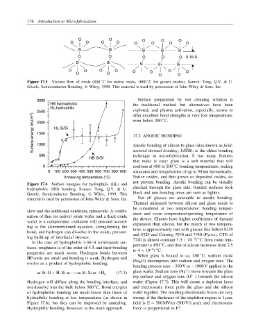
Surface energy (mJ/m 2 ) 2000 HL Si/Si 17.2 ANODIC BONDING
offer excellent bond strengths at very low temperatures,
◦
even below 200 C.
1500
1000
assisted thermal bonding, FATB), is the oldest bonding
500 Anodic bonding of silicon to glass (also known as field-
technique in microfabrication. It has many features
HB Si/Si
that make is easy: glass is a soft material that will
0 conform at 400 to 500 C bonding temperatures, sealing
◦
0 100 200 300 400 500 600 700 800 900 structures and irregularities of up to 50 nm hermetically.
Annealing temperature (°C) Native oxides, and thin grown or deposited oxides, do
not prevent bonding. Anodic bonding can be visually
Figure 17.6 Surface energies for hydrophilic (HL) and
hydrophobic (HB) bonding. Source: Tong, Q.Y. & U. checked through the glass side: bonded surfaces look
G¨ osele, Semiconductor Bonding, Wiley, 1999. This black and non-bonding areas are seen as lighter.
material is used by permission of John Wiley & Sons, Inc Not all glasses are amenable to anodic bonding.
Thermal mismatch between silicon and glass needs to
be considered at two temperatures: bonding temper-
slow and the additional oxidation, minuscule. A combi- ature and room temperature/operating temperature of
nation of thin (or native) oxide wafer and a thick oxide the device. Glasses have higher coefficients of thermal
wafer is a compromise: oxidation will proceed accord- expansion than silicon, but the match at two tempera-
ing to the aforementioned equation, strengthening the tures is approximately met with glasses like Schott 8339
bond, and hydrogen can dissolve in the oxide, prevent- and 8329 and Corning 7070 and 7740 (Pyrex). CTE of
ing build-up of interfacial stresses. 7740 is almost constant 3.3 × 10 / C from room tem-
−6 ◦
In the case of hydrophobic (–Si–H terminated) sur- perature to 450 C, and that of silicon increases from 2.5
◦
faces, roughness is of the order of 5 ˚ A and their bonding to 4 × 10 / C.
−6 ◦
properties are much worse. Hydrogen bonds between When glass is heated to ca. 400 C, sodium oxide
◦
HF-units are small and bonding is weak. Hydrogen will (Na 2 O) decomposes into sodium and oxygen ions. The
evolve as a product of hydrophobic bonding:
bonding process uses −300 V to −1000 V applied to the
+
≡ Si–H + H–Si ≡−→≡ Si–Si ≡ +H 2 (17.3) glass wafer. Sodium ions (Na ) move towards the glass
2−
top surface and oxygen ions (O ) towards the silicon
Hydrogen will diffuse along the bonding interface, and wafer (Figure 17.7). This will create a depletion layer
◦
not dissolve into the bulk below 500 C. Bond energies and electrostatic force pulls the glass and the silicon
of hydrophobic bonding are much lower than those of wafer together. The resulting electrostatic forces are very
hydrophilic bonding at low temperatures (as shown in strong: if the thickness of the depletion region is 1 µm,
Figure 17.6), but they can be improved by annealing. field is E = 500 MV/m (500 V/1 µm); and electrostatic
2
Hydrophilic bonding, however, is the main approach. force is proportional to E .