
Page 263 - Sami Franssila Introduction to Microfabrication
P. 263
242 Introduction to Microfabrication
design the patterns in one polarity and to invert Undercutting in wet etching can be compensated by
polarity computationally in the mask making pro- biasing the photomask. The patterns on the mask are
cess, but once the physical mask plates have been made wider by the amount of etch undercutting for light-
drawn, the mask and resist are tied together. Expo- field structures, and narrower for dark-field structures.
sure wavelength also limits mask plate materials: at This procedure is process dependent, in the sense that it
436 nm (g-line), soda-lime glass is acceptable, but at yields good results for one film thickness. Mask biasing
365 nm (i-line) and below, quartz becomes the material can be done in a global fashion: all structures on an
of choice. aluminium level can be biased wider by, for example,
It is possible to mix lithographic techniques: this twice the designed aluminium film thickness. For a
approach is known as mix-and-match. Not all lithogra- 3 µm nominal linewidth, this translates to 5 µm wide
phy steps are equal: some are more critical than others. patterns (assuming 1 µm aluminium thickness), and thus
Critical levels determine device functionality in a crit- 1 µm etch undercutting per side. If the resolution of the
ical way, for example, CMOS gate mask determines lithography tool is 6 µm (capable of printing 3 µm lines
gate length, which affects transistor speed and leak- with 3 µm spaces), mask biasing cannot be done because
age. CMOS contact holes are critical because they have 1 µm spaces would need to be resolved. Mask biasing
to be aligned very closely to the active area and the wastes silicon real estate, and the resolving power of
gate. A single linewidth-critical level may be written the lithography tool is not fully utilized for increasing
by an e-beam, while the rest are exposed by optical device-packing density.
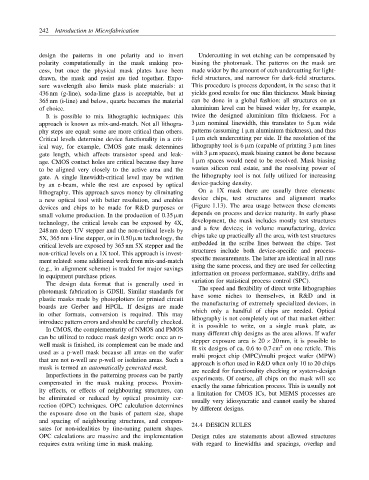
lithography. This approach saves money by eliminating On a 1X mask there are usually three elements:
a new optical tool with better resolution, and enables device chips, test structures and alignment marks
devices and chips to be made for R&D purposes or (Figure 1.13). The area usage between these elements
depends on process and device maturity. In early phase
small volume production. In the production of 0.35 µm
development, the mask includes mostly test structures
technology, the critical levels can be exposed by 4X,
and a few devices; in volume manufacturing, device
248 nm deep UV stepper and the non-critical levels by
chips take up practically all the area, with test structures
5X, 365 nm i-line stepper, or in 0.50 µm technology, the
embedded in the scribe lines between the chips. Test
critical levels are exposed by 365 nm 5X stepper and the
structures include both device-specific and process-
non-critical levels on a 1X tool. This approach is invest-
specific measurements. The latter are identical in all runs
ment related: some additional work from mix-and-match
using the same process, and they are used for collecting
(e.g., in alignment scheme) is traded for major savings
in equipment purchase prices. information on process performance, stability, drifts and
The design data format that is generally used in variation for statistical process control (SPC).
photomask fabrication is GDSII. Similar standards for The speed and flexibility of direct write lithographies
plastic masks made by photoplotters for printed circuit have some niches to themselves, in R&D and in
boards are Gerber and HPGL. If designs are made the manufacturing of extremely specialized devices, in
in other formats, conversion is required. This may which only a handful of chips are needed. Optical
introduce pattern errors and should be carefully checked. lithography is not completely out of that market either:
In CMOS, the complementarity of NMOS and PMOS it is possible to write, on a single mask plate, as
many different chip designs as the area allows. If wafer
can be utilized to reduce mask design work: once an n- stepper exposure area is 20 × 20 mm, it is possible to
well mask is finished, its complement can be made and fit six designs of ca. 0.6 to 0.7 cm on one reticle. This
2
used as a p-well mask because all areas on the wafer multi project chip (MPC)/multi project wafer (MPW)
that are not n-well are p-well or isolation areas. Such a approach is often used in R&D when only 10 to 20 chips
mask is termed an automatically generated mask.
are needed for functionality checking or system-design
Imperfections in the patterning process can be partly
experiments. Of course, all chips on the mask will see
compensated in the mask making process. Proxim-
exactly the same fabrication process. This is usually not
ity effects, or effects of neighbouring structures, can
a limitation for CMOS ICs, but MEMS processes are
be eliminated or reduced by optical proximity cor-
usually very idiosyncratic and cannot easily be shared
rection (OPC) techniques. OPC calculation determines
by different designs.
the exposure dose on the basis of pattern size, shape
and spacing of neighbouring structures, and compen- 24.4 DESIGN RULES
sates for non-idealities by fine-tuning pattern shapes.
OPC calculations are massive and the implementation Design rules are statements about allowed structures
requires extra writing time in mask making. with regard to linewidths and spacings, overlap and