
Page 114 - Microsensors, MEMS and Smart Devices - Gardner Varadhan and Awadelkarim
P. 114
MONOLITHIC PROCESSING 95
device in the linear region (i.e. V Ds < V Gs - V T, V Gs > V T), the drain current is given by
2
I D = K n [2 (V GS - VT) V DS - V DS] (4.24)
where K n is the device constant and, for an n-type MOSFET, is related to the channel
length L, width W, electron mobility u n, gate oxide capacitance C' o by
(4.25)
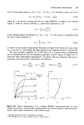
In the saturated region of operation (i.e. V DS > V Gs - V T), the device is switched on and
the drain current simplifies to
n 2
= ~ (V GS - V T) (4.26)
as shown by the transfer characteristic illustrated in Figure 4.30. Pinch-off occurs when
is less that V T, and, ideally, the drain current is zero when the device is switched off.
V GS
The basic dynamic properties of an FET device in a common-source configuration
can be characterised by the low-frequency equivalent circuit 11 shown in Figure 4.31 in
which the main small-signal conductances 12 are shown. The low-frequency gate-source,
gate-drain, and drain-source conductances are defined as
I
dI G dI G d D
and g ds = (4.27)
d V GS GS 'GD DS
Saturation
region
4 -
(V) (V)
10
(a) (b)
Figure 4.30 Typical characteristics of an n-channel MOSFET (enhancement-type): (a) drain
(output) characteristic, with dotted line separating ohmic and saturated regions of operation and (b)
transfer (input-output) characteristic in the saturated region
11
Leakage current and reactive components are ignored.
12
The subscripts used are gate g, drain d, source s, and forward f.