
Page 209 - The Geological Interpretation of Well Logs
P. 209
13
IMAGE LOGS
13.1 Generalities techniques no longer apply. With the new tools, there are
new attitudes.
Description Since the mid-eighties there has been an explosive
A fundamental new concept has been introduced into development in imaging technology, principally in terms
logging with the advent of the modern imaging tools, of tools but also in terms of producing the image. The
The formation is no longer sampled by a single sensor to progress has been linked with the availability of downhole
create a single log, it is sampled many times horizontally digitisation of signals and the possibility of transmitting
and at a high rate vertically, to form a dense matrix of large data volumes in rea] time. Where the standard logs
measurements from which is created an image. This is are sampled every {5 cm (6"), image logs may sample
not a picture like a core photo made in visible light, it is every 0.25 cm (0.1"): where the standard logs have one
a computer created image based on geophysical measure- Measurement per depth point, image logs may have 250.
ments of acoustic reflectivity or of electrical conductivity. This makes for very large data volumes, for some tools jn
The images represent formation response at the borehole the region of 200 kilobits per second transmitted up the
wall and give a continuous vertical record of the entire cable to achieve a collection rate of 60,000 samples per
borehole circumference (or as much as possible in the metre of borehole. Imaging technology is still evolving
case of the electrical images). Standard interpretation rapidly and is affecting the entire logging field.
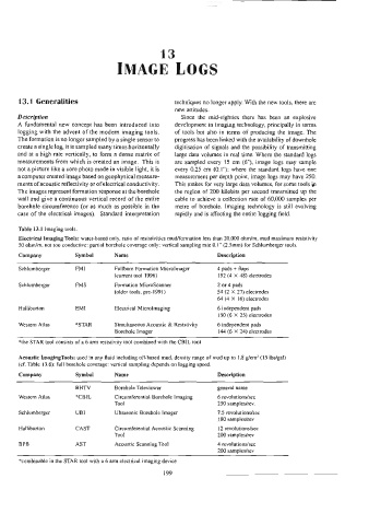
Table 13.1 Imaging tools.
Electrical Imaging Tools: water-based only, ratio of resistivities mud/formation less than 20,000 ohm/m, mud maximum rfesistivily
50 ohm/m, not too conductive: partial borehole coverage only: vertical sampling rate 0.1” (2.5mm) for Schlumberger tools.
Company Symbol Name Description
Schlumberger FMI Fullbore Formation Microlmager 4 pads + flaps
(current tool 1996) 192 (4 X 48) electrodes
Schlumberger FMS Formation MicroScanner 2 or 4 pads
(older tools, pre- 1991} 44 (2 X 27) electrodes
64 (4 X 16) electrodes
Halliburton EMI Electrical Microlmaging 6 independent pads
150 (6 X 25) electrodes
Western Atlas *STAR Simultaneous Acoustic & Resistivity 6 independent pads
Borehole Imager 144 (6 X 24) electrodes
*the STAR tool consists of a 6 arm resistivity taol combined with the CBIL tool
Acoustic LmagingTools: used in any fluid including oil-based mud, density range of mud up to 1.8 g/cm’? (15 Ibs/gal)
(cf. Table 13.6): full borehole coverage: vertical sampling depends on logging speed.
Company Symbol Name Description
BHTV Borehole Televiewer general name
Western Atlas *CBIL Circumferential Borehole Imaging 6 revolutions/sec
Tool 250 samples/rev.
Schlumberger UBI Ulerasonic Borehole Imager 7.5 revolutions/sec
180 samples/rev
Halliburton CAST Circumferential Acoustic Scanning {2 revolutions/sec
Tool 200 samples/rev
BPB AST Acoustic Scanning Tool 4 revolutions/se¢c
200 samples/rev
*combinable in the STAR tool with a 6 arm electrical imaging device