
Page 212 - The Geological Interpretation of Well Logs
P. 212
- THE GEOLOGICAL INTERPRETATION OF WELL LOGS -
Table 13.2 Borehole circumference coverage of the Schlumberger electrical imaging tools in approximate percentages.
Tool No. of electrodes Logging speed Hole diameter
6" gx" 12%"
FM] 4 pad + flaps 192 $50m/h (1800’ sh) 90% 80% 50%
FMI 4 pad 96 1 LO0m/h (3600’/h) 50% 40% 25%
FMS 4 pad 64 500m/h (1600’/h) 50% 40% 25%
FMS 2 pad 54 500m/h (1600"sh) 25% 20% 12%
SHDT dipmeter (8) 1650m/h (5400’/h)
1. Pad assemblage 2. Sensor array detail
l
PAD ae 0.3"
2a — F PEDPHD- vows
buttons so coaaoeeee 4 0.17
ei
CEVV SN _ ArTen DEPTH
VV
VV
VV
VV
VABAAALAASAARATS SHIFTING
hinged 3. Sensor button detail
ae]
eoovoveveese! | buttons insulation
electrode
button
hinge
0.24"
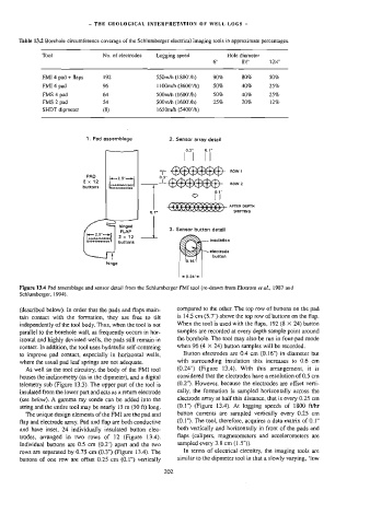
Figure 13.4 Pad assemblage and sensor detail from the Schlumberger FMI tool (re-drawn from Ekstrom ef ai., 1987 and
Schlumberger, 1994}.
(described below). In order that the pads and flaps main- compared to the other. The top row of duttons on the pad
tain contact with the formation, they are free to ult is 14.5 cm (5.7") above the top row of buttons on the flap.
independently of the tool body. Thus, when the tool is not When the tool is used with the flaps, 192 (8 < 24) button
parallel to the borehole wall, as frequently occurs in hor- samples are recorded at every depth sample point around
izontal and highly deviated wells, the pads still remain in the borehole. The too] may also be run in four-pad mode
contact. In addition, the tool uses hydraulic self-centreing when 96 (4 X 24) button samples will be recorded.
to improve pad contact, especially in horizontal wells, Button electrodes are 0.4 cm (0.16") in diameter but
with surrounding insulation this increases to 0.6 cm
where the usual pad leaf springs are not adequate.
As well as the tool circuitry, the body of the FMI tool (0.24") (Figure 13.4). With this arrangement, it is
considered that the electrodes have a resolution of 0.5 cm
houses the inclinometry {as in the dipmeter), and a digital
telemetry sub (Figure 13.3). The upper part of the tool is (0.2"). However, because the electrodes are offset verti-
cally, the formation is sampled horizontally across the
insulated from the lower part and acts as a return electrode
{see below), A gamma ray sonde can be added into the electrode array at half this distance, that is every 0.25 cm
(0.1") (Figure 13.4). At logging speeds of 1800 ft/hr
string and the entire tool may be nearly 15 m (50 ft} long.
The unique design elements of the FM] are the pad and button currents are sampled vertically every 0.25 cm
flap and electrode array. Pad and flap are both conductive (0.1"}. The tool, therefore, acquires a data matrix of 0.1"
and have inset, 24 individually insulated button elec- both vertically and horizontally in front of the pads and
trodes, arranged in two rows of 12 (Figure 13.4). flaps (calipers, magnetometers and accelerometers are
Individual buttons are 0.5 cm (0.2") apart and the two sampled every 3.8 cm (1.5")).
rows are separated by 0.75 cm (0.3°) (Figure 13.4). The In terms of electrical circuitry, the imaging tools are
buttons of one row are offset 0.25 cm (0.1") vertically similar to the dipmeter tool in that a slowly varying, ‘low
202