
Page 78 - The Ultimate Palm Robot
P. 78
Color profile: Generic CMYK printer profile
Composite Default screen
Bots /The Ultimate Palm Robot/ Mukhar & Johnson / 222880-6 / Chapter 3
Chapter 3 Building the Robot 61
the charger and plugging the charger into an electrical socket. This will ensure
that the batteries are ready for you when the robot is complete.
Building the Frame
Start by finding the IR rangers, and the parts to connect the ranger to the alu-
minum frame. For each ranger you will need two 5/8-inch screws, two nylon
washers, two nylon spacers, two lock washers, and two nuts. These parts will
be in bag one of the kit. Attach one ranger to each aluminum frame piece. Start
by inserting both screws through the frame, then adding the washers and
spacers. Place the sensor onto the screws and fasten it with the lock washers
and nuts.
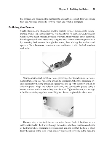
Now you will attach the three frame pieces together to make a single frame.
Notice that each piece has a long arm and a short arm. When the pieces are ori-
ented correctly, the long arm on one piece will line up with the short arm on an
adjacent piece. Align the holes in each arm, and connect the pieces using a
screw, washer, and a nut from bag two of the kit. Tighten the nuts just enough
to hold everything together; we will tighten them completely in a later step.
The next step is to attach the servos to the frame. Each of the three servos
will be attached to the frame through the rectangular hole that is on each side
of the frame where the frame pieces connect. You can see that the hole is offset
from the center of the side; when the servo is placed correctly in the hole, the
P:\010Comp\Bots\880-6\ch03.vp
Monday, May 12, 2003 4:41:25 PM